LED Troffer Retrofit: Specifying the Profile for a Ceiling You Cannot Change
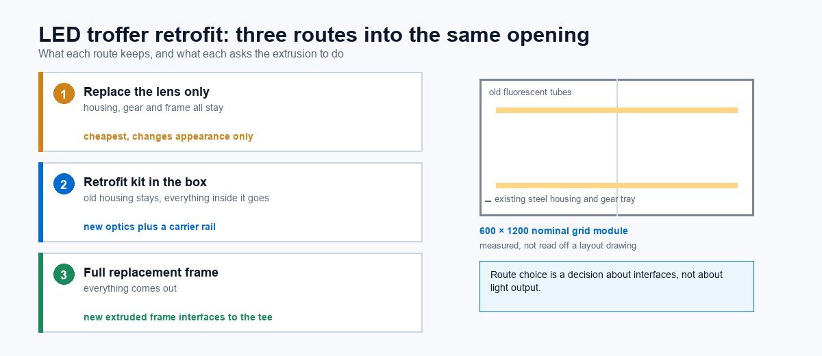
Abstract: In a retrofit the building sets the dimensions, not the luminaire. This article takes a recessed modular ceiling as the worked case and walks what the extruded profile has to do across three routes: replacing only the lens, dropping a retrofit kit into the existing housing, or replacing the whole fitting with a new extruded frame. It covers why nominal grid sizes are not the sizes you measure, what removing the ballast actually changes in the housing, why glare usually gets worse after an LED conversion rather than better, and the four items that belong on the drawing for any project fitting new light into an old opening.
Retrofitting is a constraints problem, not a product problem
New construction is easy. The ceiling is on paper, nobody has occupied it yet, and if a dimension needs to change somebody changes it before the first panel goes up.
Retrofit inverts that. The building is finished, occupied, and in many cases legally retained. The opening exists at a size nobody chose recently, the plenum above it contains things you cannot move, and every hour spent above the ceiling line costs somebody money or goodwill. The fitting is the only variable left.
That has one important consequence for a profile designer. You are not designing a luminaire that happens to fit a ceiling. You are designing something that fits an opening whose real dimensions you have to go and measure, often across a building where several generations of installation mean “nominally identical” fixtures are not identical at all.
The good news is that this constraint sits mostly in the extrusion, and extrusions are the cheapest part to get right.
Start with the opening
Three things about the existing ceiling decide almost everything downstream.
The nominal module. Recessed modular ceilings are built around grid modules, most commonly 600 mm and 1200 mm squares and rectangles, which carry the old two-foot and four-foot heritage sizing. Two that met grilles is the everyday pattern, with one-by-one or one-by-two variants in corridors and older buildings. A layout drawing will tell you which, but it will not tell you what the actual opening measures.
What sits above it. Plenum depth governs how much fixture you can put back in. Old fluorescent troffers were shallow; if the plenum carries ductwork, conduit and a fire damper, there may be less room than the drawing suggests. Some retrofit routes need clearance that simply is not there, and finding that out with a tape measure is much cheaper than finding it out with a pallet of product on site.
Access. Open-ceiling working, occupied-building rules, working hours restrictions and whether panels can be lifted individually all change how much assembly can happen above the grid versus below it. A profile that has to be installed from below, in pieces, through a ceiling tile opening is a genuinely different product from one that drops in complete.
Three routes, and what each asks of the extrusion
Almost every project lands in one of these.
Direct replacement optical part. Keep the original housing, keep the original frame if it is sound, and replace only the lens or diffuser that has yellowed, crazed or gone brittle. Cheapest, fastest, least disruption, and it does nothing about the light source. Usually driven by appearance rather than performance, and popular in buildings where the fluorescent gear was replaced relatively recently.
Retrofit kit into the existing housing. Strip the old tubes, gear and reflector, then fit LED boards and a new optical element mounted to something that attaches to the old housing. The old box becomes a mechanical container and, depending on how it is done, a heat path.
Full replacement with a new extruded frame. The entire fitting comes out and a new one goes in, usually lighter and shallower, sized to the same visual opening. Most freedom, highest cost per unit, and the route most projects pick once they accept that the thirty-year-old steel housing has already had its life.
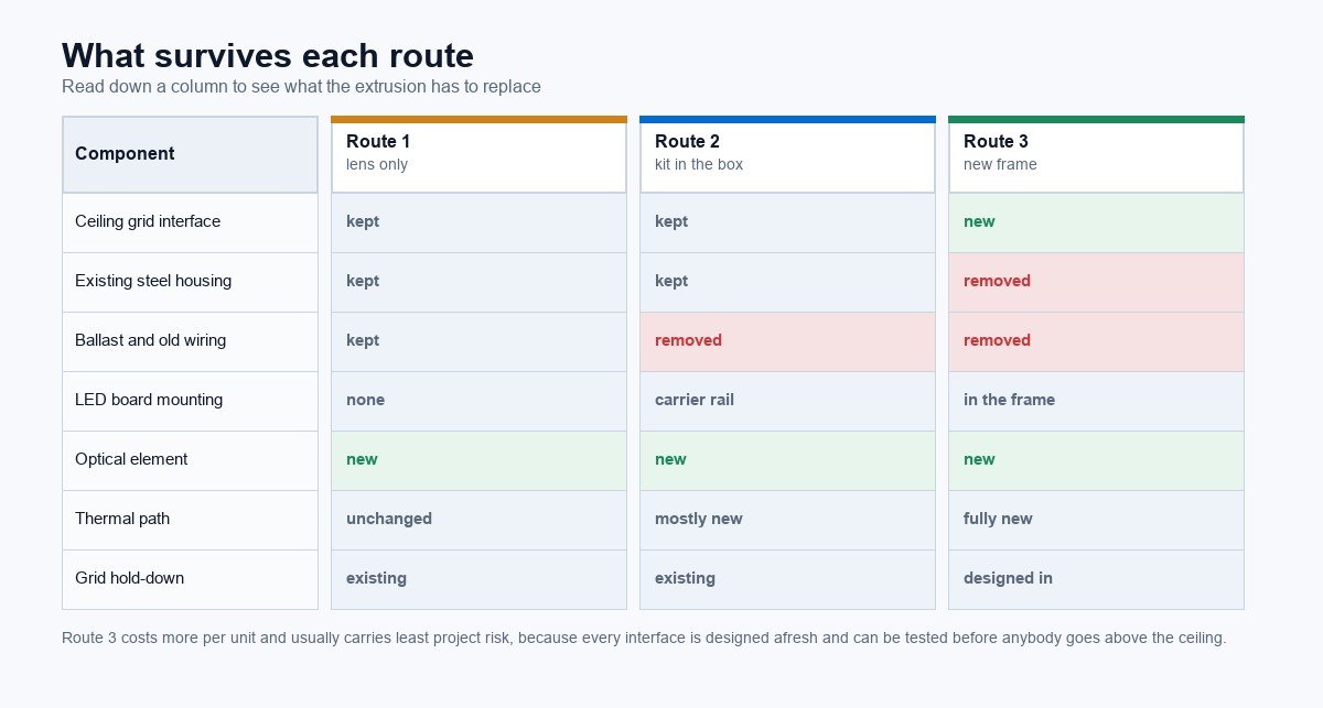
The extrusion matters in all three, but its job changes. In the first it is purely optical and mechanical. In the second it carries structure and possibly heat. In the third it carries everything, including the interfaces to the grid.
Route one, replacing only the lens
This is where most projects think they are, and the appeal is obvious. Nothing electrical changes, no certification work, no licensed trades except swapping the part.
What makes it harder than it sounds is that the part being replaced is often twenty or thirty years old and undocumented. The original lens geometry was designed around fluorescent tubes, which are large-diameter diffuse sources several centimetres off the surface. Put linear LED boards behind it and you have a line source very close to the surface, and the two behave completely differently.
Three practical points.
First, get a physical sample, not a drawing. Old lenses were made by processes with their own shrink behaviour, and the piece you are replacing may not match its nominal section anywhere closely.
Second, decide whether you are copying or improving. Copying gets you back to the appearance everyone has lived with, including whatever glare characteristics came with it. Improving means changing the section, and any change to a diffuser section changes the glare calculation, often not in the direction the client expects.
Third, check what the old material has become. Brittle acrylic that has been under fluorescent UV for two decades will crack on removal, and mottled yellowing across a ceiling sometimes indicates a thermal history worth understanding before new parts go in. The mechanisms in why diffusers yellow are worth knowing here, because distinguishing an old UV problem from a heat problem tells you whether the replacement will suffer the same fate.
Route two, the kit inside somebody else’s box
The appealing thing about keeping the existing housing is that the grid interface stays untouched. The difficult thing is that the extrusion now has to attach securely to something that was never designed to receive it.
Three questions decide whether this route works.
Where does the board mount? Ideally to something with thermal mass, ideally metal, and ideally mechanically rather than with adhesive. If the old housing is light-gauge steel with a painted interior, thermal contact through it is poor and adhesive mounting is a maintenance problem waiting to happen. An extruded carrier rail that bridges between the housing walls usually solves this, and it is a natural custom profile job.
What holds the new optical part? It has to retain reliably and it has to be removable, because somebody will eventually open it. Snap features that were fine for a one-and-done factory assembly are not necessarily fine for a ceiling that gets opened for cleaning twice a year.
Does the old housing still have structural life? If the sheet metal is corroded at the corners or the end plates have been bent repeatedly, you are building on poor foundations, and no amount of clever extrusion compensates.
Where the existing enclosure stays sealed, check what that does for temperature. Running LEDs inside a volume designed to hold fluorescent tubes changes the airflow picture, and shortcuts here show up as premature depreciation. Material selection follows from that, and the PC versus PMMA comparison is the practical reference once you know the working temperature.
Route three, the new frame
For anything beyond a simple office plug-in replacement, this is often genuinely the least risky option despite the higher unit cost, because every interface is designed afresh and can be tested before installation.
What the extrusion carries in this configuration is more than the company expects:
- the grid interface, meaning the flange geometry that sits on the ceiling tee
- rigidity across the opening, since once the old housing is gone the fitting has to hold its own shape
- the optical element, usually as a snap-in or slide-in diffuser
- often the gear tray or the board mounting
- sometimes the IP rating interface if it is going into a damp or cleanable space
This is where the extrusion earns its keep, because all of those are things a profile designer can put into a single section. A frame that mounts to the tee, carries the board, accepts a snap-in diffuser and covers the ceiling cut edge is one part doing five jobs, and that is what a custom extrusion is for.
The dimension problem nobody budgets for
This deserves its own section because it costs projects real money.
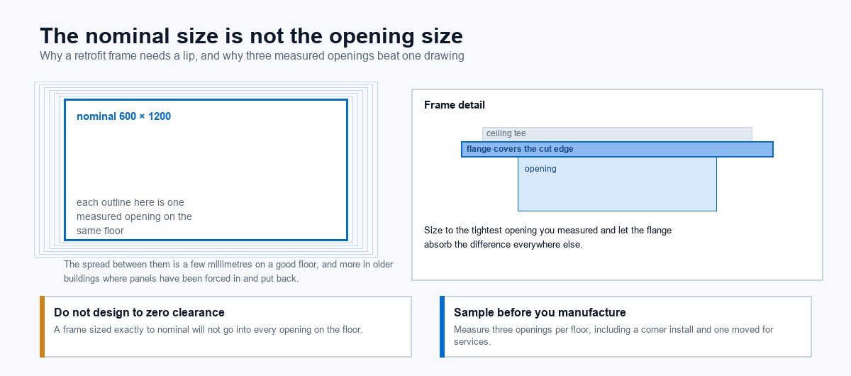
The nominal module size is not the opening size. Grid ceilings are built to nominal dimensions with real tolerances, buildings move, replacement panels get forced in, and thirty-year-old housings get bent and put back. In practice a floor of nominally identical openings will measure a few millimetres apart in both directions, occasionally more in older buildings.
Two consequences.
Do not design to zero clearance. A frame sized exactly to nominal will not go into every opening on the floor. Either size to the tightest realistic opening with a lip that covers the rest, or build adjustability into the flange.
Sample before you manufacture. Ask for three openings across the floor to be measured and photographed, ideally including one corner install and one that has been moved for services. This is not bureaucracy. It is the cheapest insurance available on a retrofit job, and suppliers who ask for it are doing their job.
The tolerance discussion in full is covered separately in the extrusion tolerance article, and what belongs on a drawing generally is set out in the profile drawing checklist. Both are worth reading before sending anything out for quotation.
What removing the ballast changes
Most people think of ballast removal as an electrical job, and mostly it is. It also changes the physical design in four ways that land on the extrusion.
Space. The ballast occupied volume, usually in a channel along the centre of the old housing. Remove it and you have a longitudinal cavity. Most retrofit designs use it for either the LED driver or the board mounting, and knowing which before designing the section avoids a redesign.
Wiring route. Old gear had mains going to the ballast and separate wiring to the lampholders. After conversion everything converges on the driver and then the boards. If new cable is being pulled through existing holes, know where those holes are.
Weight. A new fitting usually weighs less than what came out. That is normally good, but a much lighter unit in a ceiling that relied on fixture weight or had wire supports can move, and occasionally the new design needs hold-down features to sit correctly against the tee.
Maximum box temperature. Removing the ballast removes a heat source from the enclosure, which usually helps, but the gear box still holds a driver, and the driver’s stated ambient figure is worth checking against what actually happens above a ceiling in summer.
Glare gets worse before it gets better
Worth telling clients in advance. A fluorescent troffer hid four large tubes behind a prismatic panel, and the resulting luminaire had low luminance spread over a wide area. Replace that with LED boards behind the same style of panel and you often get visible bright lines, higher peak luminance, and complaints about discomfort in spaces that were previously fine.
Retrofitting into offices makes this acute, because the complaint arrives from people sitting at screens. The office lighting application notes cover what matters in that environment, and the UGR selection article sets out why higher transmission frequently means worse glare rather than better light.
The profile-side responses are ordinary: deeper optical cavity, higher diffusion, a lens array rather than a flat diffuser, or occasionally a change from a symmetric to a batwing distribution. The troffer lighting pages show the range of sections that get used for this. All of them are cheaper decided at the drawing stage than after installation.
Four things to put on the drawing
Practical summary, and it applies whichever route you take.
- Measured opening range, not nominal. Give the tightest and loosest dimension across sampled openings, plus the corresponding ceiling type and whether the tee is recessed, flush or tegular.
- Plenum depth and obstacles. Clearance above the grid, plus anything within it that constrains height or lifting path.
- Assembly direction and frequency. Whether it installs from below or above, whether it must come down for cleaning, and how often. This drives retention design.
- What is staying and what is going. Existing housing retained or removed, ballast removed or not, existing emergency provision, and anything else that constrains the electrical layout.
Anything else the profile supplier needs is covered in the drawing checklist, and for continuous stream alongside retrofit situations there is the linear lighting application material.
Where this leaves the project
Retrofits reward the people who measure first. Every problem in this article, apart from the fundamental material ones, traces back to someone assuming a dimension instead of going up a ladder with a tape measure, or assuming the diffuser designed for fluorescent tubes would suit the source it now sits over.
Do that measuring early and the rest is a normal custom extrusion job: pick the route, resolve the interfaces, choose the material against working temperature and cleaning regime, and get a sample into a real opening before committing to production.
The sample before production sequence and what to check at each gate is set out in the six week programme article, which is the right frame for most retrofit projects. When you have your measurements and your route, send them through request a quote and we will tell you which part honestly needs to be custom, and which is a standard section already in the catalogue.
What to measure before a retrofit lens can be specified
A retrofit is the reverse of a new design: the housing already exists and cannot be moved, so the profile has to be built around measurements taken in a ceiling. Five of them decide whether the job is straightforward.
| Measurement | Why it decides the design | How to record it |
|---|---|---|
| Housing opening, inside the retention feature | Sets the maximum section width. Our production runs to about 400 mm across the section, so width is rarely the limit — the retention geometry is. | Measure the clear opening, not the nominal housing size, and photograph the corner. |
| Retention method | Snap, slide-in or a captured edge. This decides the feature geometry and whether the lens can be replaced without dropping the housing. | Photograph the existing lens in place and out, with a scale. |
| Length and how it is cut | Retrofit lengths are often non-standard. Cut-to-length is a secondary operation with its own tolerance. | State the length and the acceptable cut tolerance separately. |
| Existing lens material and condition | Yellowed acrylic tells you something about the UV and heat the position sees — useful input for the replacement material. | Send a sample of the old lens if it can be removed intact. |
| Optical target | Transmission range and glare requirement, not a single transmission number. | State as a range plus any UGR or uniformity target for the room. |
Four mismatches that stall a retrofit on site
What to put on the drawing
- Clear opening dimensions, measured, with the corner detail.
- Retention method, with photographs of the existing lens in and out.
- Length and cut tolerance, stated separately.
- Material — PC where impact or heat dominates, PMMA where transmission and UV stability do.
- Transmission range and glare target, not a single transmission figure.
- Quantity and whether this is a one-off retrofit or a repeat programme, because that decides whether a dedicated die is worth cutting.
Related reading: troffer lighting applications, choosing a linear diffuser that passes UGR, and diffuser or lens for linear fixtures.