Diffuser or Lens: Choosing Optics for Linear Fixtures
Abstract: A diffuser scatters light to hide the emitter, and every percent of diffusion is paid for in transmission. A lens redirects light to shape the beam, and every degree of shaping is paid for in uniformity along the run. Most linear fixtures need both, in different proportions, and the most common optical mistake is using one to fix a problem the other created. This page sets out the trade-off with numbers you can put on a drawing, and the three combinations that work.
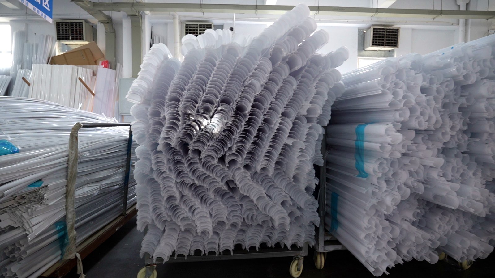
What each one actually does
| Diffuser | Lens | |
|---|---|---|
| Job | Scatter light in all directions so the emitter is not visible | Redirect light into a defined distribution |
| Effect on transmission | Falls as diffusion rises — the light is redirected, and some of it exits the back face | Falls less, but only inside the shaped beam; outside the beam it is zero |
| Effect on uniformity | Improves along the run and across it | Usually improves along the run, can worsen across it |
| Effect on UGR | Lowers it, because the emitting surface luminance drops | Depends on the distribution: a wide batwing lowers it, a narrow beam raises it |
| What you cannot do with it | Aim light | Hide an emitter that is badly spaced |
The row that decides most projects is the last one. Neither element substitutes for the other, and no amount of optic design fixes an emitter pitch the diffuser was supposed to hide.
The transmission cost, stated plainly
Diffusion is not free and it is not linear. Moving from a lightly textured clear surface to a heavily opal one can remove a large share of the light before it leaves the fixture, and the last few percent of hiding power is the most expensive. The practical consequence:
- If the emitter pitch is small and the setback is generous, a light prismatic texture hides it and keeps most of the light.
- If the pitch is large or the setback is short, you need heavier diffusion — and the fixture loses efficiency that no driver setting recovers.
- If you are already at the edge of the efficacy target, the answer is usually to change the geometry (setback, pitch, mixing chamber) rather than to specify a heavier diffuser and accept the loss.
Three combinations that work
1 · Prismatic diffuser, no lens
The workhorse for linear and troffer. The prism spreads each emitter along the run, hides the pitch and lowers UGR. Cheapest per metre, and the right answer more often than suppliers admit.
2 · Lens section with a light diffusing skin
A lens geometry carries the beam, and a fine texture on the outer face takes the sparkle off the emitter image. Costs less light than a full opal and keeps the distribution.
3 · Co-extruded: lens zone plus diffuser zone
One section with a clear lens strip and an opal strip side by side. Used where the fixture has an accent zone and a general zone, or where the end caps need to glow without a visible emitter.
Where the two cancel each other out
Stacking elements is where efficiency disappears. Two cases worth avoiding:
- An opal secondary optic behind a prismatic cover. The prism already spreads the image; the opal then scatters what the prism shaped. The transmission losses multiply, and the distribution you designed is no longer the distribution you get.
- A lens section behind a heavy diffuser film. The film destroys the directionality the lens was cut to produce. If the film is needed for glare, the lens is probably unnecessary — and vice versa.
The test is simple: state which element owns the distribution, and make the other one do a different job. If both are shaping the beam, one of them is being wasted.
What goes on the drawing
| Line on the drawing | Why it matters | Typical wording |
|---|---|---|
| Function | Tells the toolmaker which way the surface faces and what it must achieve | “Diffuse, emitter not visible at 300 mm” |
| Material | Sets the transmission ceiling before any texture is applied | “PMMA, optical grade” or “PC, flame retardant” |
| Surface | Prism side in, smooth side out — or the reverse | “Prism to LED side” |
| Transmission target | Converts “bright enough” into something inspectable | “≥ 85% at 3 mm, measured per section” |
| Marked critical dimensions | The ones that set the optical path | Wall over prism, prism pitch |
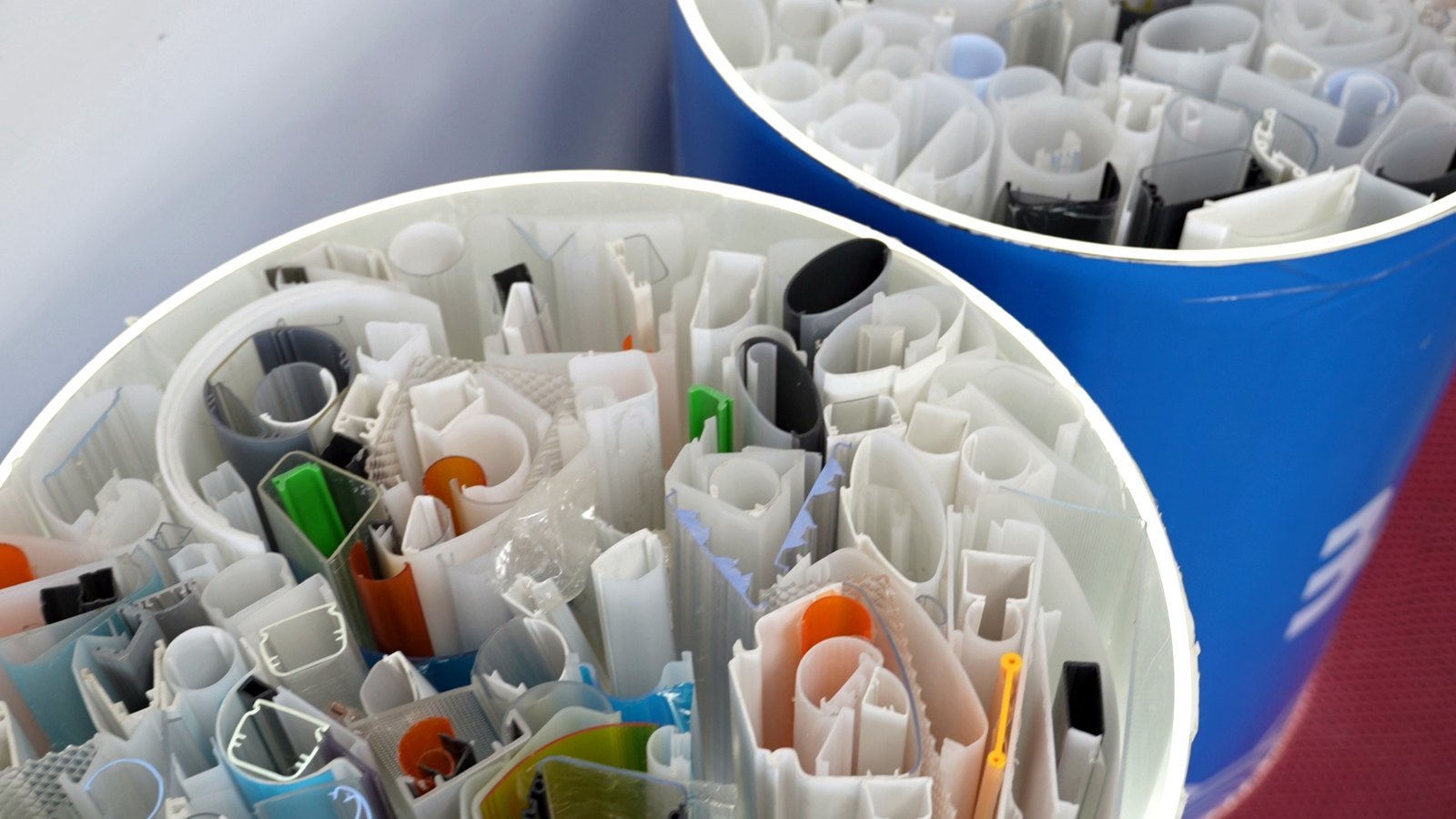
Frequently asked questions
Can one profile be both a diffuser and a lens?
Partly. A prismatic section diffuses in the sense that it hides the emitter, and it also shapes the light along the run. What it cannot do is produce a defined two-axis distribution. If the fixture needs a photometric file with a specific curve, the section alone will not get there.
Does a diffuser always reduce UGR?
It lowers the luminance of the emitting surface, which is the main driver of UGR, so usually yes. But UGR also depends on the room, the mounting height and the viewing angle. A diffuser that lowers surface luminance while widening the distribution can still leave you above a UGR 19 limit in a small office.
How do I know the diffuser will hide the LEDs?
By testing the actual combination: emitter pitch, setback distance, section, and viewing distance. Calculation gets you close, a physical sample settles it. We cut sections from the die so the test uses the real geometry rather than a catalogue approximation.
Which material for a diffuser, PC or PMMA?
PMMA transmits more and stays clearer, so it is the default where efficiency matters. PC takes impact and holds flame-retardant grades, so it is the default for industrial, tri-proof and vandal-resistant fixtures. The full comparison is in PC vs PMMA for lighting profiles.
Next step
Tell us the emitter pitch, the setback and the viewing distance you need to hide, and we will recommend a section and a texture rather than a generic “opal”. Request a quote, or start from custom LED diffuser profiles.