Does an LED Profile Need a Heat Sink? PC and PMMA Temperature Limits
Abstract: Extruded polycarbonate and acrylic are optical parts, not thermal ones, and a linear fitting that runs too warm will show it long before anything fails outright. This article separates the two numbers that get confused on a material data sheet, heat deflection temperature and continuous use temperature, gives representative working ranges for PC and PMMA, and walks through where heat actually goes in a linear profile. It sets out when a plastic extrusion on its own is fine, when an aluminium carrier belongs in the design, what the snap-fit features do as they warm, and the information worth asking a supplier for before a drawing is frozen.
Why heat decides how long a linear fitting lasts
An LED almost never dies dramatically. It dims.
The failure mode that removes a lighting installation early is not a component snapping, it is gradual depreciation: lumen output falls year on year until somebody decides the space feels tired and replaces the whole thing. Temperature is the largest single accelerator in that process, ahead of drive current and ahead of duty cycle.
This matters for the extruded profile because the profile is usually the last thing between the heat source and the room. The profile determines whether hot air leaves, whether the board sits in an insulating pocket, and how long “long” turns out to be. A diffuser specified purely for transmission and appearance can quietly become the reason a fitting runs fifteen degrees warmer than the designer’s thermal model assumed.
None of this requires exotic analysis. It requires knowing what the material tolerates and being honest about the conditions inside the housing.
What heat does to an extrusion, in order of how often it causes trouble
Four things happen, and melting, which is what people worry about, is not one of them.
Yellowing and haze. Every polymer degrades faster as it gets warmer, and the visible evidence is usually first a shift toward yellow and a loss of transmission. Thermal degradation is a different mechanism from UV degradation, but they look similar from the outside, which is why the two get blamed on each other. The in-service mechanisms behind discolouration in LED diffusers operate alongside the ones driven purely by running temperature, and separating them on a returned sample takes a bit of care.
Creep and sag. This is the one that surprises people. Hold a thermoplastic under load near its limit and it does not fail, it slowly deforms. A long diffuser supported only at the two ends, warm for thousands of hours, can begin to bow in the middle. It is completely recoverable in appearance terms until someone looks up the run and sees a gentle smile where there should be a straight line. Sag is reported far more often than actual rupture, and it is also regularly misdiagnosed as a tolerance problem.
Snap-fit relaxation. Most fixtures hold the diffuser with a resilient lip or a row of fingers moulded or extruded into the profile. Those features work by staying slightly deflected. Warm them past their comfortable range for long enough and they relax, the retention force drops, and a cover that used to click firmly starts lifting at the ends. Nothing has broken, you just can no longer trust it to stay in.
Dimensional movement. PC and PMMA expand with temperature at roughly six to eight parts in a hundred thousand per degree, several times aluminium’s rate across the same span. In a long run with fixed end plates that translates into real length change, and into a case for leaving the expansion somewhere to go. Worth noting that this is not a defect in the material. It is arithmetic, and it belongs on the drawing rather than in a complaint later.
The two data sheet numbers people mix up
Ask a supplier “what temperature will this take” and you will often get one of two numbers, and they are not interchangeable.
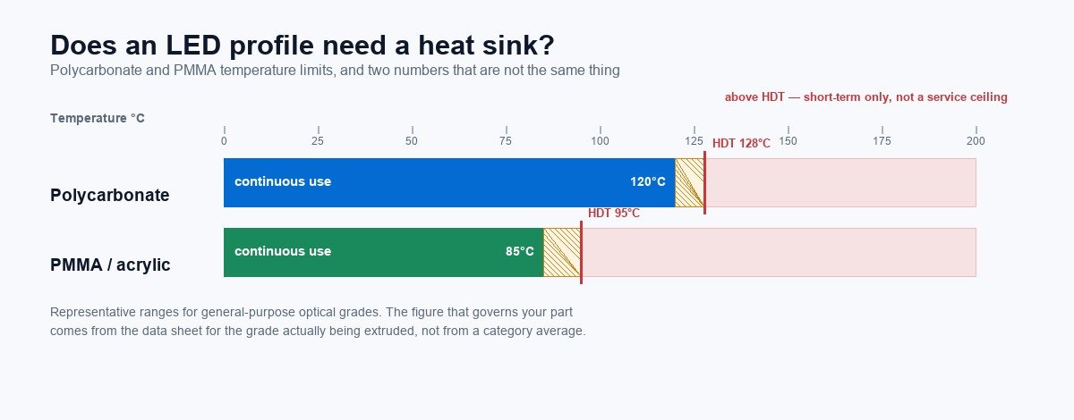
Heat deflection temperature, usually abbreviated HDT, comes from a short-term test. A bar is loaded to a specified stress, heated at a fixed rate, and the temperature at which it deflects by a set amount is recorded. It is a useful comparison tool between grades and it tells you almost nothing about service life. An HDT quoted at one load condition does not transfer to another, and a part that survives its HDT briefly can still creep indefinitely below it.
Continuous use temperature, sometimes appearing as a relative thermal index on material documentation, is the number you actually want. It describes what the material tolerates indefinitely without losing its properties in a way that matters. It is usually well below HDT, and the gap between the two is not a safety margin you can spend.
Representative ranges for general-purpose optical and extrusion grades, quoted for orientation rather than for a specific purchase:
| Polycarbonate (PC) | PMMA / acrylic | |
|---|---|---|
| Heat deflection temperature, commonly quoted | roughly 125–130 °C | roughly 85–100 °C |
| Continuous use temperature, typical | roughly 115–125 °C | roughly 80–90 °C |
| What it means for a diffuser | survives a demanding enclosed fixture | comfortable in standard interiors, worth checking in hot ones |
Treat those as conversation starters, not specifications. The number that governs your part comes from the data sheet for the grade actually being extruded, and any supplier quoting you a material should hand it over without a discussion.
PC versus PMMA, in the terms that matter here
The comparison usually gets made on optics and cost, and it should also be made on temperature.
PC carries the higher ceiling of the two, and keeps its shape where acrylic starts to soften. It takes abuse better, which is worth something in public environments and in anything that might be knocked. The trade-off is that it yellows more readily in service and is more susceptible to certain cleaning agents and to stress cracking when it is put under sustained load near a solvent.
PMMA has better optical stability and, in most comparisons, holds its transmission and colour longer under UV. It scuffs more easily and it gives up its shape at a lower temperature. In a standard interior linear fixture at normal drive levels, that lower ceiling rarely gets touched. In a high-output enclosed fitting, or one mounted above a heat source or in direct sun behind glass, it does.
The material choice pages go into this in detail from the optical direction, both for lighting profiles generally and for light covers specifically, and the polycarbonate and PMMA material pages carry the associated properties.
Where the heat goes, and why plastic is not a heat sink
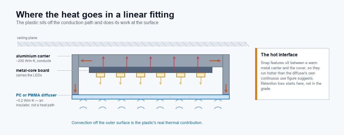
The conduction path in a linear fitting is short and easy to describe. Heat leaves the diode, crosses into the metal-core circuit board, travels to whatever the board is mechanically mounted against, and then leaves that into room air by convection and radiation.
Along that path there is one number that decides whether an extruded profile helps or hurts. PC and PMMA conduct heat at somewhere around 0.2 watts per metre-kelvin. Aluminium runs around two hundred. That is roughly a thousand-fold difference, and it means a plastic extrusion is never going to move meaningful heat away from anything. It is a thermal insulator, and pretending otherwise produces designs that look plausible and run hot.
This is not a criticism of plastic. Three honest jobs belong to it:
- Convection surface. The outer face of the profile is what touches room air. Giving it area and letting air move across it does real work, and a profile shape that traps a still air pocket does the opposite.
- Insulation. Keeping a warm enclosed volume away from a surface that people touch is a feature, not a compromise. This is one reason plastic housings show up in public transport interiors and anywhere a hand can reach.
- Optics. Transmission, diffusion, glare control and appearance, which is the reason the part exists.
A design that expects the plastic to conduct heat to somewhere else is a design with an aluminium part missing.
When the plastic profile alone is enough
More often than the thermal discussion suggests, honestly. A lot of well-designed fittings run the diffuser nowhere near a material limit.
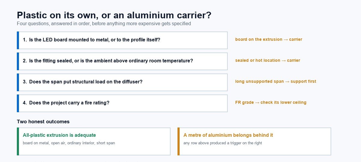
The extrusion alone is usually adequate when most of these hold: the LED board already has its own metal core and is mechanically fixed to the housing or to the ceiling structure, the profile is not the structural path for heat, the fitting is not sealed tight against airflow, drive levels are moderate, ambient conditions are ordinary indoor ones, and the span between supports is short enough that the extrusion is not load-bearing across it.
A diffuser in a suspended linear fixture with the board screwed to a metal tray satisfies all of those. So does a lens array above a board mounted to an aluminium carrier. In these cases adding a finned aluminium section behind the diffuser buys nothing measurable, and designers who add it anyway are spending money out of anxiety.
When an aluminium carrier belongs in the design
There are configurations where the answer changes, and they are recognisable enough to list.
High power per unit length. When the wattage per metre climbs, the board needs a conductive path that plastic cannot provide, and the profile above it is along for the ride.
Sealed or gasketed enclosures. Once a fitting is sealed to an ingress rating, the trapped volume heats itself. Everything above assumes some air movement. A fully sealed IP65 or IP67 profile deserves a genuine thermal look rather than a comparison against open fixtures.
Elevated ambient. Industrial ceilings, fittings above ovens or process equipment, outdoor luminaires in direct sun in hot climates. The relevant calculation is board temperature plus ambient temperature together, and the second term is the one that gets forgotten in temperate test rooms.
Long unsupported spans. When sag rather than heat is the immediate concern, the fix is often support rather than material change. Worth checking which problem you actually have before specifying a more expensive polymer.
Fire-rated compounds. Worth knowing that adding flame retardant packages changes other properties. If your project carries a rail or public transport requirement, check the flame retardant profile discussion on what those grades give up.
The hybrid most linear fittings actually use
The common resolution is not either-or. Aluminium takes the board, does the conducting and the structural work, and a PC or PMMA extrusion snaps into it to handle optics, touch temperature and appearance. This is why so many linear products look like a metal tray with a plastic or for that matter a co-extruded lid.
What governs this design is not whether the plastic conducts. It is whether the snap features survive. Because they sit at the interface between a warm aluminium carrier and the cover, they operate at the highest temperature in the assembly, often higher than the diffuser’s own specified continuous use figure would suggest. If retention loss shows up in field returns, this interface is the first place to look, not the material grade.
Specifying it without guessing
Five things go on the drawing or into the enquiry, and none of them require you to run a thermal model.
- Named grade with its data sheet, not a generic material family. Ask for both the HDT and the continuous use number for the grade being extruded, and ask at what load condition the HDT was measured.
- Temperature at the profile’s inner wall in the worst realistic case, not typical. Suppliers can usually tell you what similar installations have measured.
- Support span and how the diffuser is retained. Sag and snap-fit retention are both geometry questions as much as material ones.
- Worst-case ambient. Say whether the fitting sits in sun, above a heat source, or in an enclosed volume, and by how much the local air runs above general room temperature.
- Ingress rating, because it decides whether air can move.
Material documentation is worth asking for at the same time. Our certificates and material documentation page sets out what we can supply on request, including the distinction we insist on keeping clear: a UL94 classification belongs to the material manufacturer’s grade, not to a finished profile we extrude, and any thermal figure has to come from the grade data sheet rather than from a certificate.
Reading a quote when temperature is in play
Because heat changes the material, it also changes the price. A switch from a general-purpose PMMA to a higher-temperature grade, or to PC, moves the resin cost and sometimes the tooling. It also changes the tolerance conversation, because different materials shrink and recover differently through the die.
When two quotes for apparently the same profile differ materially, ask which resin each assumes. That is sometimes the entire explanation, and it is a legitimate reason for a price difference rather than a reason to reject the higher one. More on how such differences are built up is set out in the cost breakdown for extrusion quotes.
Before you freeze the drawing
The useful habit is to treat temperature as a design input rather than a test result. Decide what the application actually demands, choose the material against that, then ask for the numbers that confirm it, and check that the retention geometry still works when the assembly is warm.
If you are at the drawing stage, the questions in the custom LED profile design guide list what makes a specification answerable without a round of emails, and anything thermal belongs on that list. Where the profile needs to sit alongside length, straightness and appearance requirements, the linear manufacturing notes cover what gets specified together.
Bring us in early enough to say no to something and we usually can. Send the drawing and the duty conditions through request a quote and we will tell you whether the material you have down will hold up, or whether the honest answer is a metre of aluminium behind it.
What to specify so heat is settled before tooling
Thermal problems are almost never a material defect. They are a specification gap: nobody wrote down the service temperature, the clearance, or what happens to the section when the driver compartment runs hot for eight hours. Three lines on the drawing prevent most of it.
| Clause | What to state | What it prevents |
|---|---|---|
| Service temperature range | The air temperature the profile will see in the installed fixture, including the worst case in a sealed housing. | Specifying against room temperature when the product runs hot. The two materials diverge sharply here. |
| Clearance to heat sources | Distance from driver, board and any heat spreader, shown on the drawing with the mating parts. | Local hot spots that no material choice can rescue. |
| Wall thickness at the thinnest point | Not the nominal wall. Thin corners and light-exit faces are where distortion starts. | A section that passes first article and deforms in service. |
| Mounting and support spacing | How the profile is held, and at what centres. | Sag and bow in long runs once the section is at temperature. |
| Operating duty | Continuous or switched, and the on-hours if known. | Cycling stress that only appears after months of switching. |
Four thermal failures that only appear after installation
What to put on the drawing
- Service temperature range, including the enclosed-housing worst case.
- Clearance to driver and board, dimensioned, with the mating parts named.
- Minimum wall thickness at every critical face.
- Support spacing for long runs.
- Duty cycle — continuous or switched, and the daily on-hours if the fixture is on a schedule.
- Material choice with the reason: PC where impact or temperature dominates, PMMA where transmission and UV stability do. If the brief genuinely needs both, ask about a co-extruded section before the die is cut.
Related reading: PC vs PMMA selection matrix, what to expect from acrylic profiles, and polycarbonate material notes.