LED Strip Light Extrusion: Channel, Cover and Mounting
Abstract: The extrusion around an LED strip does four jobs at once — it carries the strip, it hides it, it decides what the light looks like, and it holds the whole thing to a surface. Most disappointing strip installations fail on the third or the fourth, not on the first two. This page works through channel, cover and mounting in that order, sets out the trade-offs at each step, and finishes with the lines your drawing needs before a channel profile can be quoted.
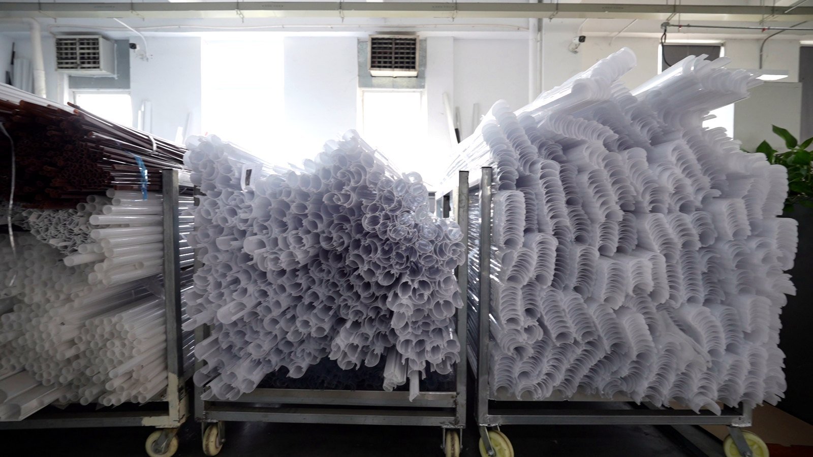
Three decisions, in order
| Decision | What it controls | What goes wrong when it is left late |
|---|---|---|
| Channel depth and width | Whether the strip sits flat, how much heat can leave, and whether dotting is visible. | A shallow channel over a dense strip shows hot spots. Depth is easier to set on paper than to add later. |
| Cover optics | How much light comes out, and whether individual emitters are visible. | A clear cover chosen for maximum output shows every diode. A diffusing cover chosen late means a second tooling round. |
| Mounting method | Surface clip, recessed, suspended or a corner — and whether it is visible. | The section is right and the fixing is impossible to install. Mounting belongs on the first drawing, not the second. |
Each of those is a tooling decision, not a finishing detail. A channel that is too shallow, a cover that is too clear and a mounting that cannot be fitted are three different reasons to cut a second die — and all three are visible on a first-article sample if the drawing says what the section has to do.
Four ways a strip channel disappoints
What to put on the drawing
- Strip width and pitch, and the diode density, because that sets the depth needed to kill dotting.
- Channel depth, with the strip seated.
- Cover type — clear, diffusing or opal — and the transmission range you need.
- Mounting method, drawn, including whether the fixing may be visible.
- End caps and continuous-run joints, drawn, because that is where runs usually fail visually.
- Material and colour, plus whether the section is indoors only or exposed to daylight.
How the programme runs
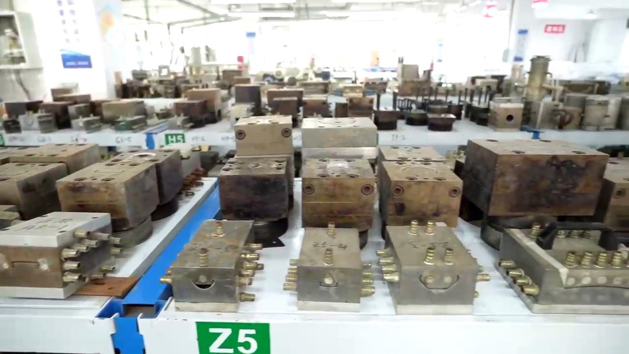
Standard sequence: drawing review, die design and manufacture, first-article samples with measurement, then production after approval — roughly six weeks from an approved drawing to first production parts on a new section, with a minimum order quantity of 500 units. We work to ±0.1 mm on marked critical die dimensions, and transmission across roughly 0 to 97 % depending on the cover construction.
Heat, duty and where a strip channel shortens LED life
A channel is also a heat path, and this is the part that gets skipped when the brief is written around appearance. LED strip life is governed by the temperature at the diode junction, and the extrusion sits directly on the thermal path between the strip and the room.
- What the channel is mounted to matters as much as the channel. Aluminium-backed strip on a metal surface sheds heat; the same strip in a plastic channel on plasterboard does not. State the mounting surface.
- A covered channel is an enclosed volume. A clear cover over a high-output strip in a shallow channel traps heat by design. If the duty is continuous, say so — the section can be given more depth or the cover specified differently, but only before tooling.
- Duty cycle belongs on the drawing. Continuous, switched, or on a timer with known hours. Thermal design without a duty cycle is guesswork.
- Long runs accumulate. Heat at the middle of a continuous run is not the same as heat at the ends, which is another reason to specify support spacing and joint method together.
None of this is exotic. It is four lines on a drawing that stop a channel being re-cut for thermal reasons after it has already been re-cut for optical ones.
Frequently asked
Clear or diffusing cover? Clear for maximum output where the emitters are not visible or are not meant to be hidden; diffusing where dotting would show. If you are unsure, specify the transmission range you need and the distance at which the run must look continuous — those two answer it.
Can the channel be painted or anodised after extrusion? The section can be finished, but the finish has to be part of the specification: paint and anodising change dimensions slightly and interact with the cover retention. Say which faces may be finished.
Do I need a new die for a different length? No. Length is a cut-to-length operation with its own tolerance; the die is per section, not per length. That is why the length and the cut tolerance are quoted separately from the tooling.
What if the strip changes supplier mid-programme? Tell us before the die is cut. Strip width, pitch and diode density all affect channel depth and cover choice, and a change after tooling can mean a second die.
Lead time, tooling and what happens next
A channel is a simple section and the tooling reflects that, but the sequence is the same as any custom profile: drawing review, die design and manufacture, first-article samples with measurement, then production after approval — roughly six weeks from an approved drawing to first production parts, with a minimum order quantity of 500 units.
Two things shorten the second round and one lengthens the first. What shortens it: sending the strip datasheet, and settling the cover type before the die is cut. What lengthens it: changing the cover optics after first article, because transmission and diffusion are built into the section, not applied to it.
If the programme is likely to need several channel sizes, say so at the start. Family tooling — one die concept across related sections — is a different conversation from three separate dies, and it only works if it is planned before the first one is cut.
Related reading: LED strip lighting applications, diffuser or lens for linear fixtures, and specifying a diffuser that passes UGR. Ready to price a channel? send the drawing.